
THE PROCESS
HARDWARE AND TOOLS USED
- 3D STUDIO MAX 2016
- CURA
- Ultimaker 3
- Needle nose plier, Flush cutter, Sanding paper.
- Cubify Sense from 3D Systems.
- Sense software from 3D Systems
- Black PLA filament
( 3D PRINTING ) INDIVIDUAL ASSIGNMENT
MODELING THE OBJECT IN 3D
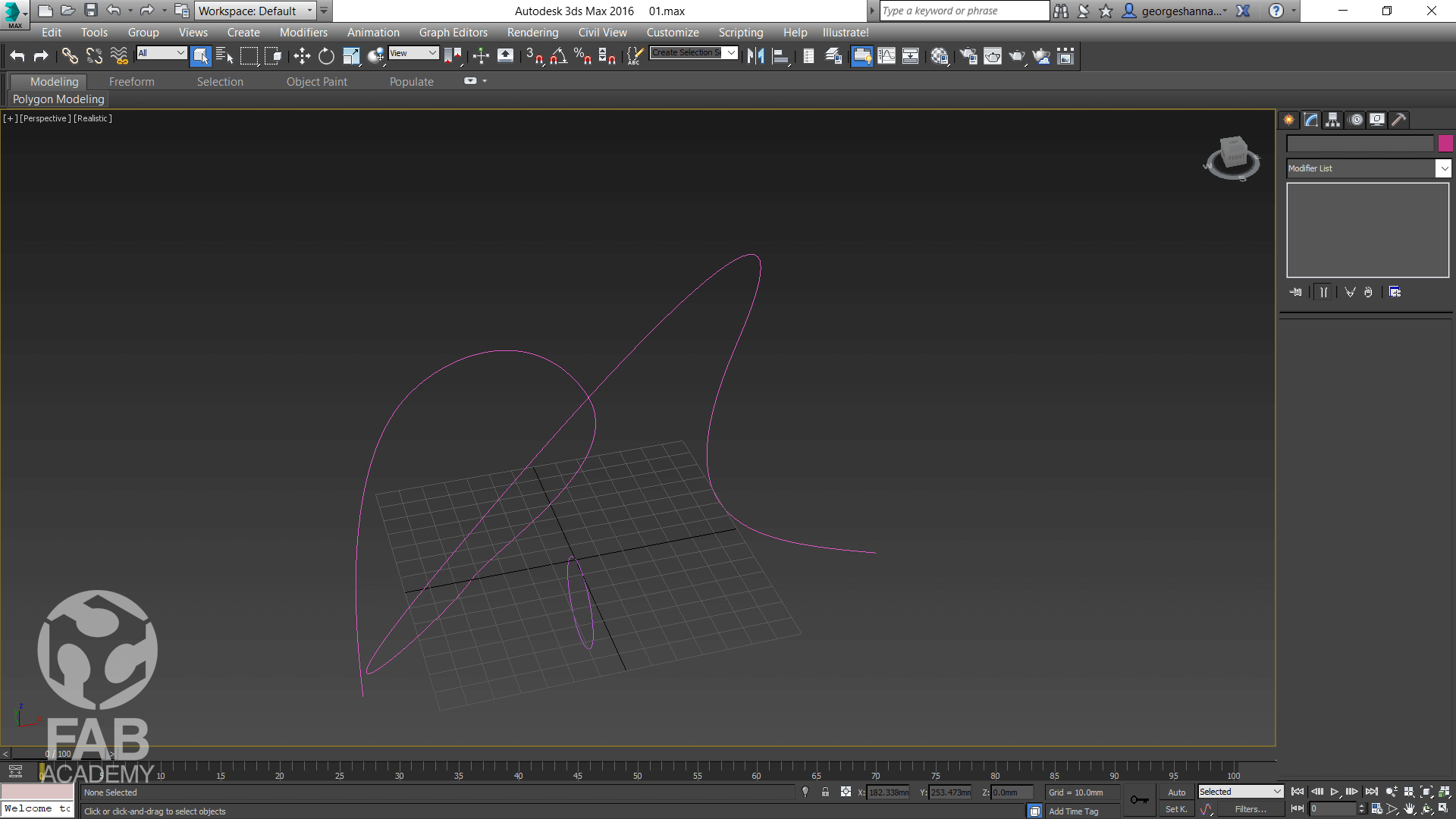
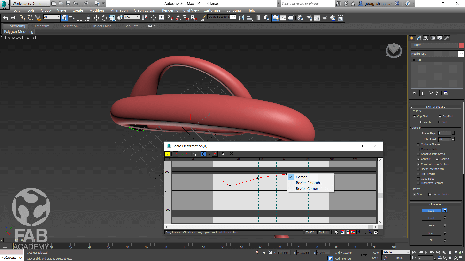
To start with, For this assignment I used 3DS MAX because I'm familiar with using this software however first, I started drawing some shapes in 3D Studio MAX and to do so I used a simple 2D shapes a line and circle and I used a tool called loft tool in order to allow the circle (cross sections) to follow the specified spline path I drew. So loft tool simply allow You to create loft objects from two or more existing spline objects. One of these splines serves as the path. The remaining splines serve as cross sections, or shapes, of the loft object. As you arrange shapes along the path, 3ds Max generates a surface between the shapes. And then I edited the deformation curves for the X axis in order to have variety of thickness of the cylinder. After finalizing the design I exported the object in G-CODE format in order to be 3D printed using PLA Black filament material.
PREPARING THE OBJECT TO BE 3D PRINTED
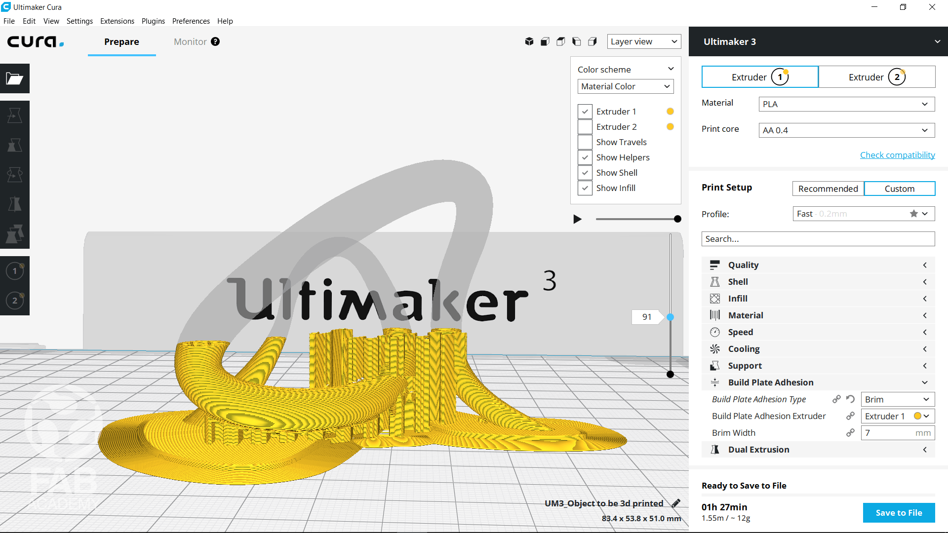
After finliazing the design and exporting it in STL format I imported it into CURA Cura is a 3D printer slicing application and it is the preferred slicer software for Ultimaker 3d printers, but can be used with other printers as well.
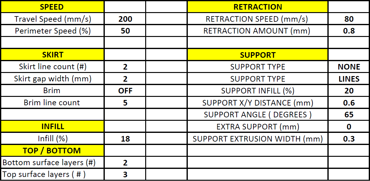
In order to print the file properly I had to adjust some sitting in Cura therefore, I started with choosing correct material. In my case I wanted to use PLA material for printing the model because it gives me a high printing speed without any harmful fumes during printing and it has a shiny and smooth appearance. Then from the profile menu I chose fast printing profile in order to speed the process up and to save material.
Below you can find all the settings I applied before printing the file in 3D :
- Material : PLA
- Print core : AA 0.4
- Profile : Fast
- Generate support : ✔
- Support Extruder : Extruder 1
- Build plate adhesion : ✔
- Support placement : Everywhere
- Built plate adhesion type : Brim
- Brim width : 7 mm
- Wall thickness : 1 mm
- Infill density : 20 %
- Printing tempreture : 205 °C
- Build plate temperature : 60 °C
I chose to use a wall thickness of 1 mm since my 3D model is small and it is full of rounded corners so its form gives it rigidity that is why I did not use a higher wall thickness value with higher value the wall become thicker and much more rigid but it takes usually more time to print and as a result it cost more money as for the infill density which define the amount of plastic used on the inside of the object I used 20 % because of the smallest section diameter of my cylindrical shaped 3D object.
The printing temperature along with the build plate temperature were adjusted be default since they are linked to the profile setting and I did not have to adjust them.
While I was adjusting the settings the software was updating the printing time simultaneously and once I finished adjusting the settings the estimated time for printing the file was 1 h 27 min. Finally, I saved the file in G-code format and uploaded it to a USB flash drive.
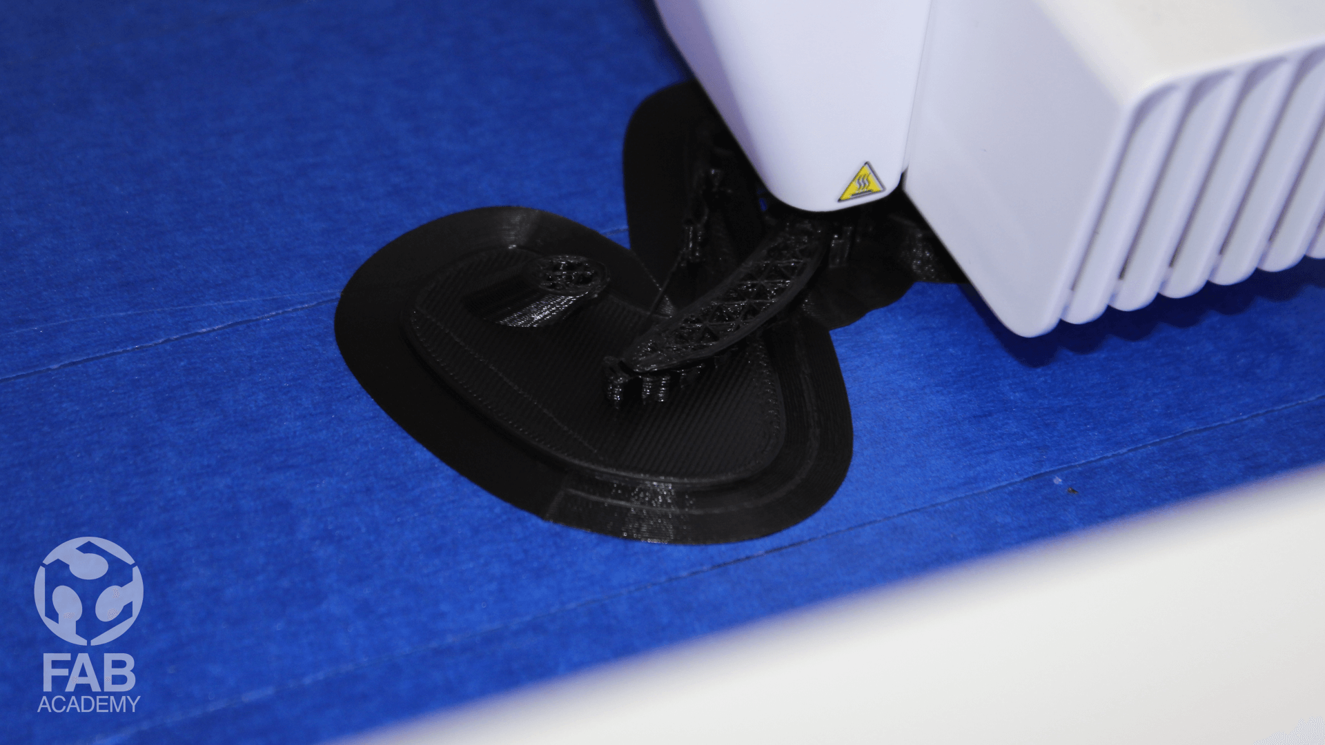
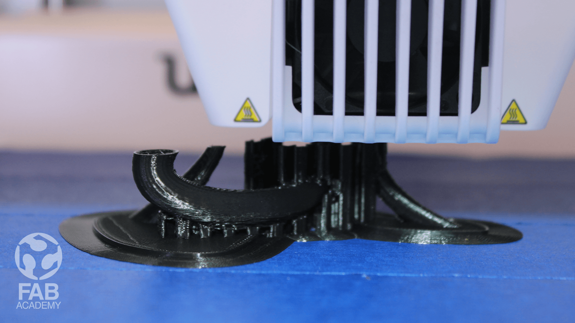
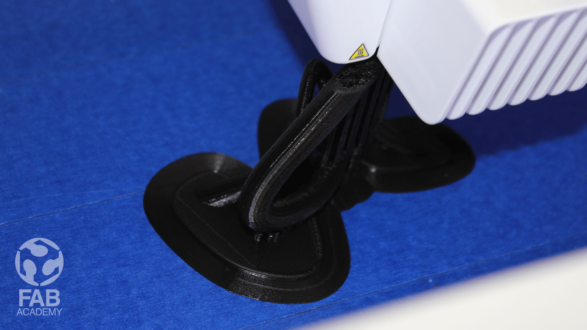
PRINTING THE FILE IN 3D
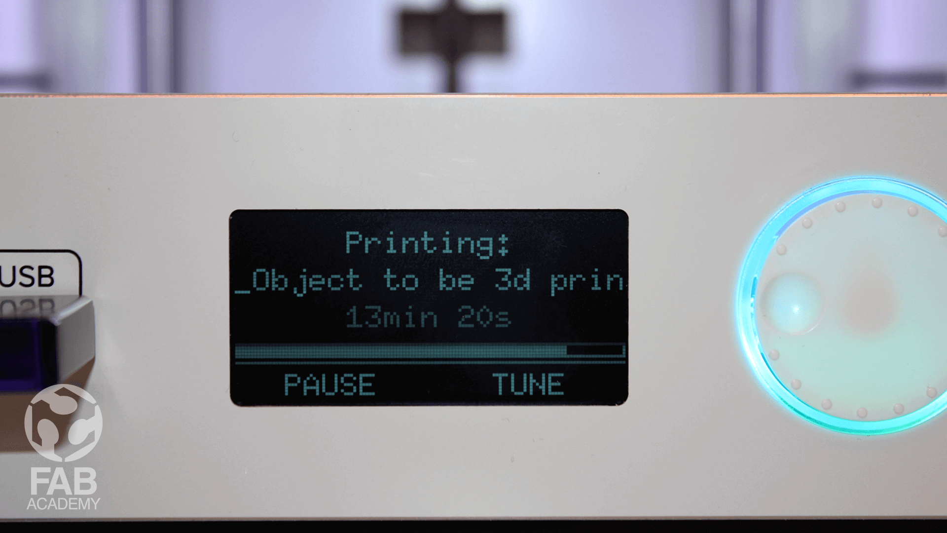
Printing the file was pretty easy, After saving the file on the USB drive I plugged it into the printer and from the printer little LCD Screen I selected the file that I wanted to print and pressed the button to start. and then I chose the print file , the Ultimaker 3 prepared itself by homing the print head and build plate and heating up the build plate and nozzle. Sometimes this can take up to 5 minutes. And while printing, the display was showing the progress of the print and the remaining time for completion. When the print had finished, I waited for the build plate to cool down before grabbing the print from the build plate.
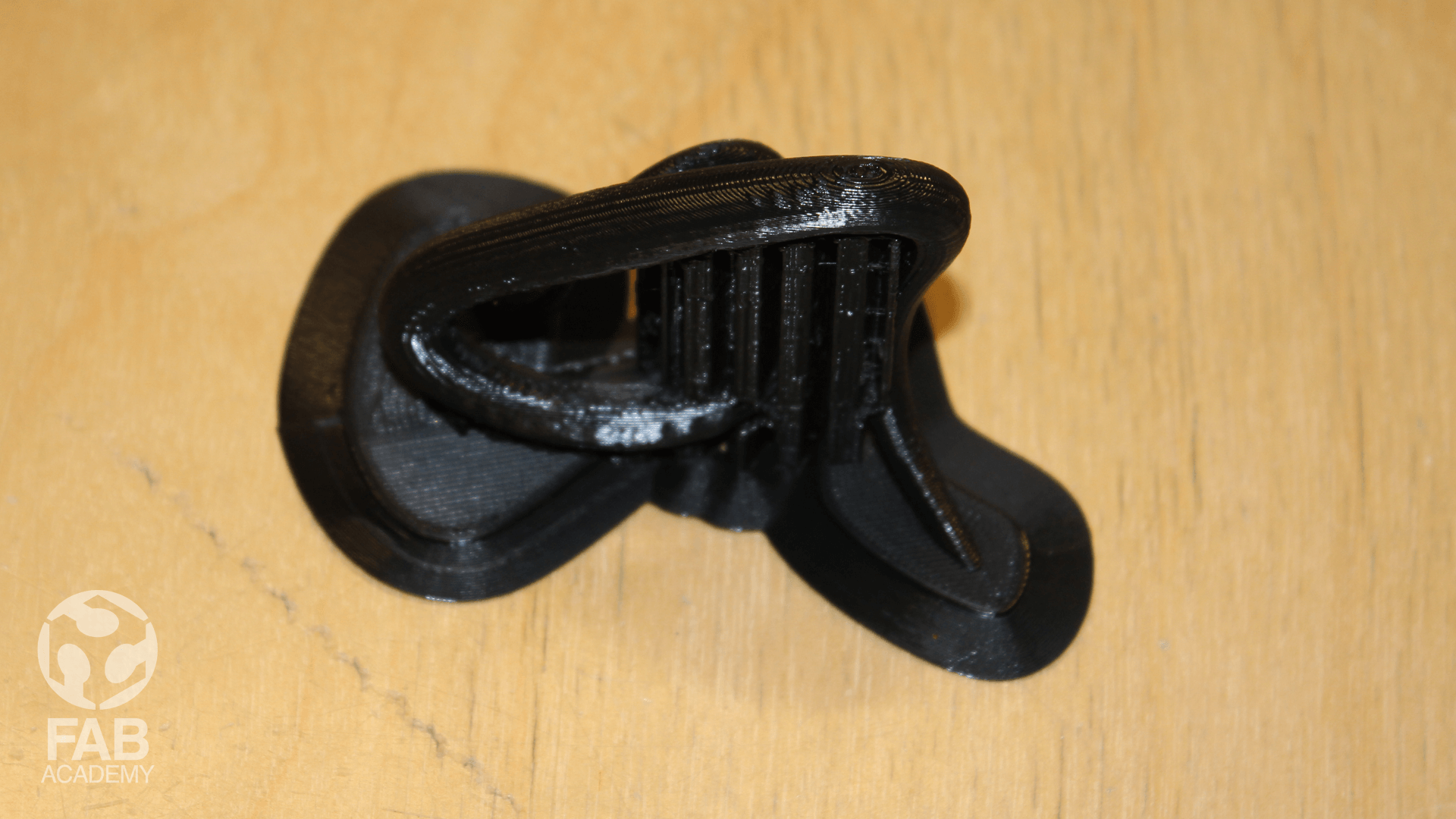
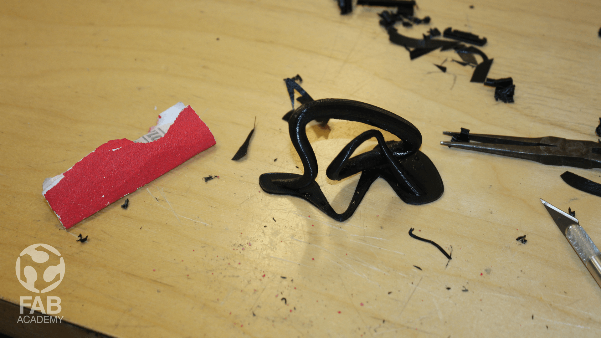
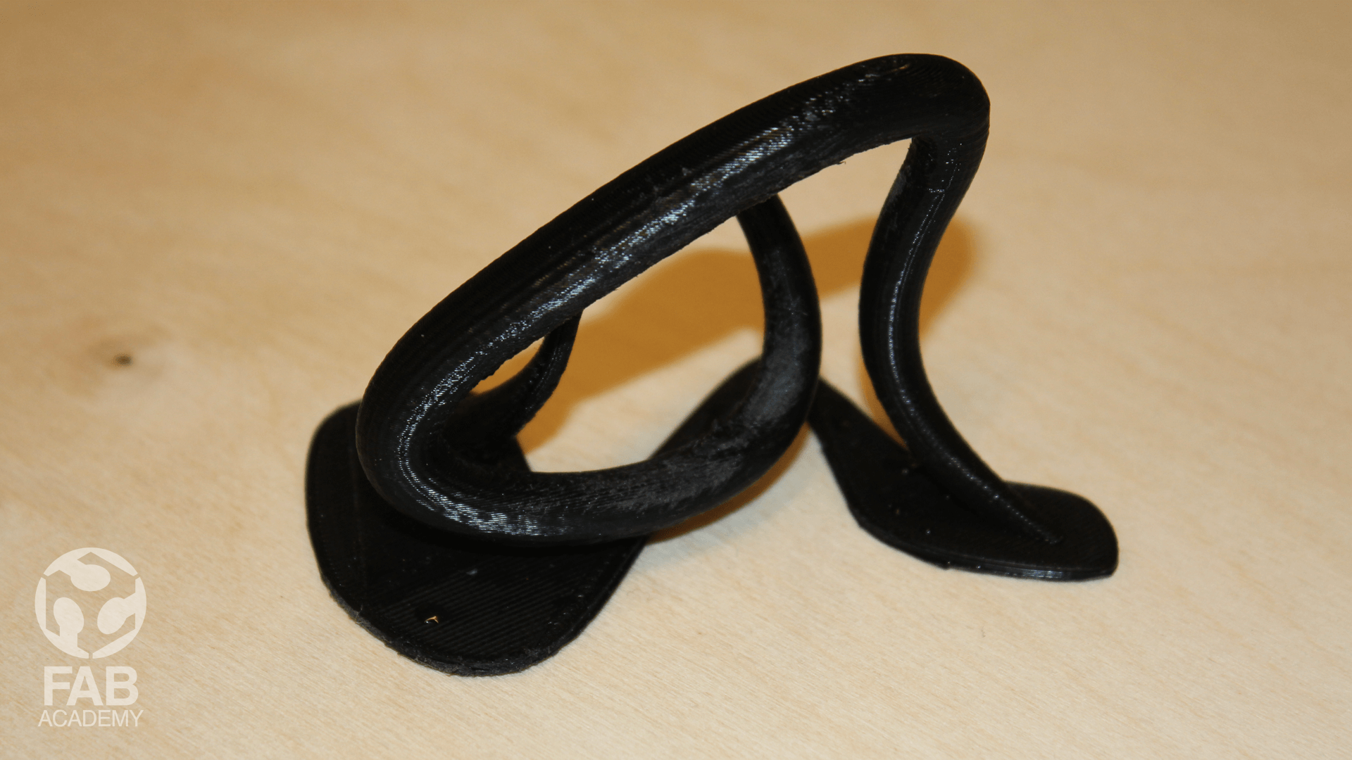
FINISHING THE 3D MODEL
The last part of the printing process was removing the supports and finishing the model for this task I used few hand tools like needle nose pliers , Flush cutter and sanding paper I used sanding paper in order to smooth down the surface and to remove some of the unwanted marks in general this was an easy process and the overall look of the model was great exactly as I expected. overall I was really satisfied with the printing quality The end result was really impressive and appealing it is like magic in few clicks you have a tangible object out of nothing isn't that cool I believe 3D printing will play an important role in the future of fabrication and rapid prototyping I can not imagine getting the this assignment done using a cnc machine ( subtractive manufacturing ) Because of many restrictions like the complexity of form and the curvatures that have many tinny corners and overlapping surfaces where they are almost touching each other it would be almost impossible to machine this part using a subtractive manufacturing process in one go. Bellow is a list of the some advantages of using 3d printing : + Manufactures complex shapes + Low entry cost + Can make multiple parts at once + It Reduces Waste Production Briefly speaking, The production process of additive manufacturing process is pretty fast, high end and relatively speaking it is cheap comparing to subtractive manufacturing
( 3D PRINTING ) GROUP ASSIGNMENT
PRINTING THE FILE IN 3D
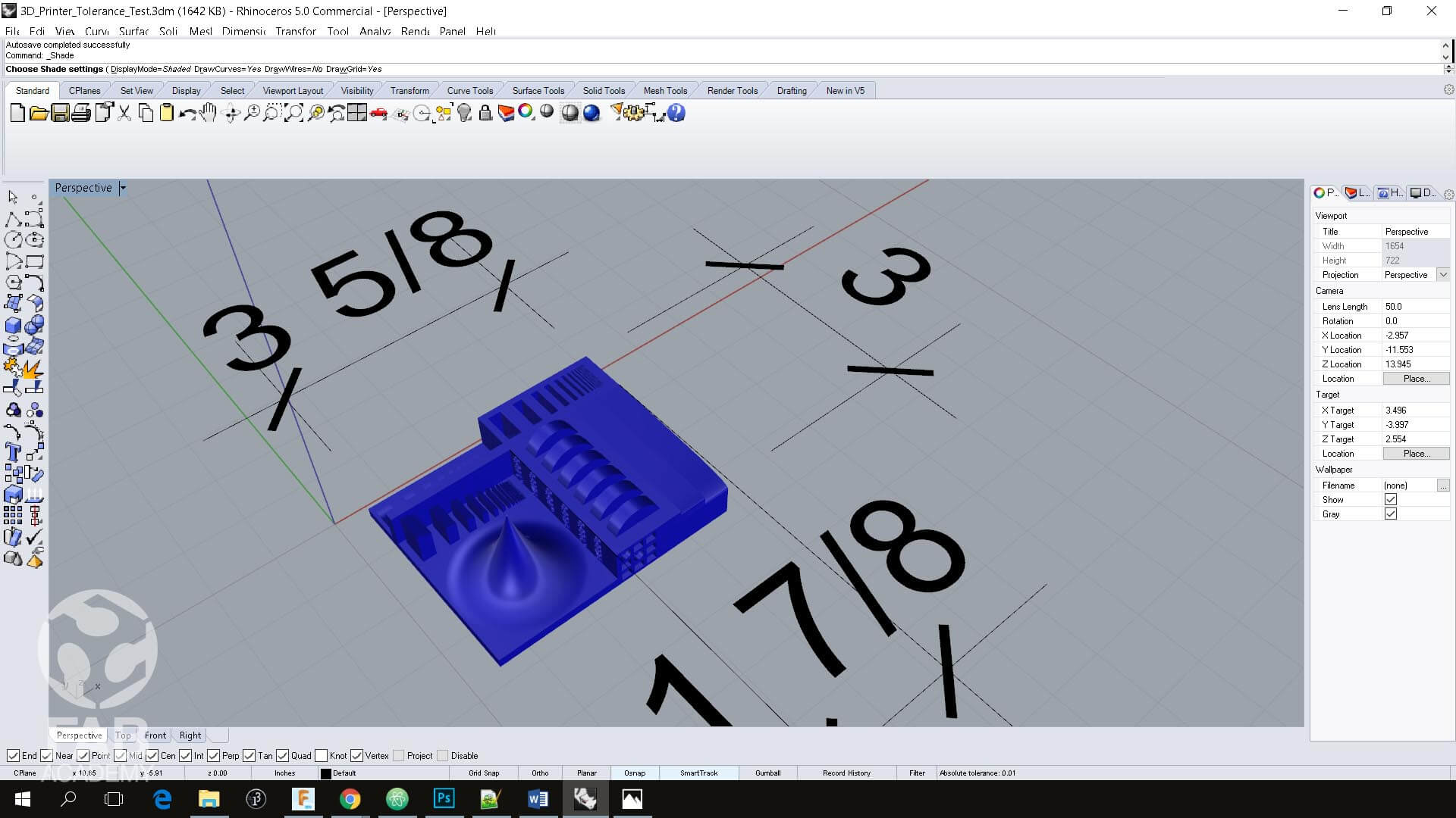
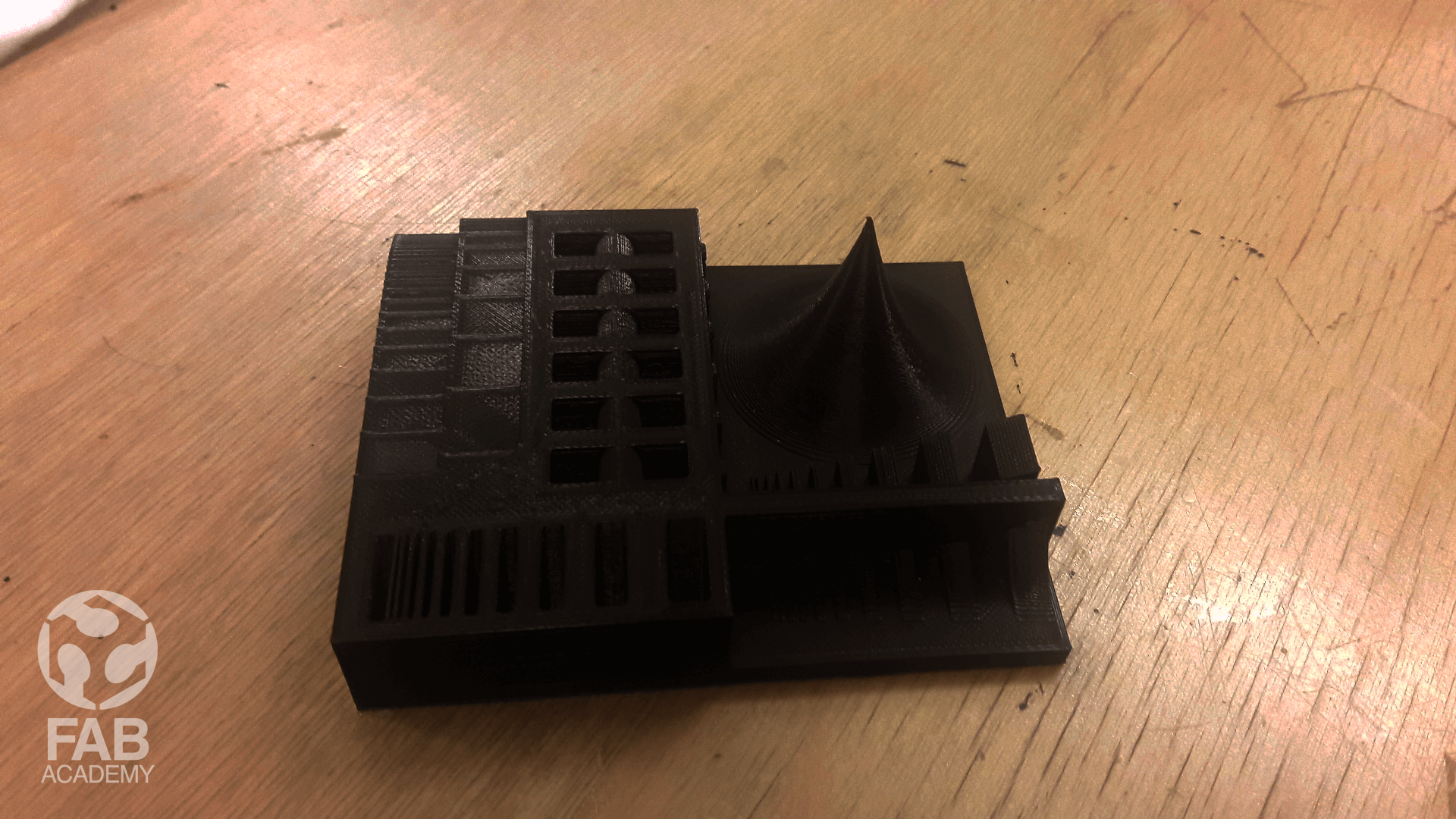
As a group project our assignment was to 3D print a Tolerance test model
In order to test the printers resolution and capabilities .
For this task we decided to run the printing tests with 2 different printers so we used Ultimaker 3 and Ditto-Pro .
For running 3D printing tests we used a 3d model that was done by amandaghassaei and posted on thinkgivers.com as we are not using the 3D model for commercial purposes we were able to use it for our printing test.
HERE.
Both parts were sliced at medium quality (0.15) and we used two different softwares for printing CURA for the Ultimaker and Tinkerine for Ditto-Pro
Both 3D prints took around 7 hours and a half to print my friends Marc and Alec printed the model at their fablabs machines
since we had to 3d print the models in the weekend and our fablab was closed.
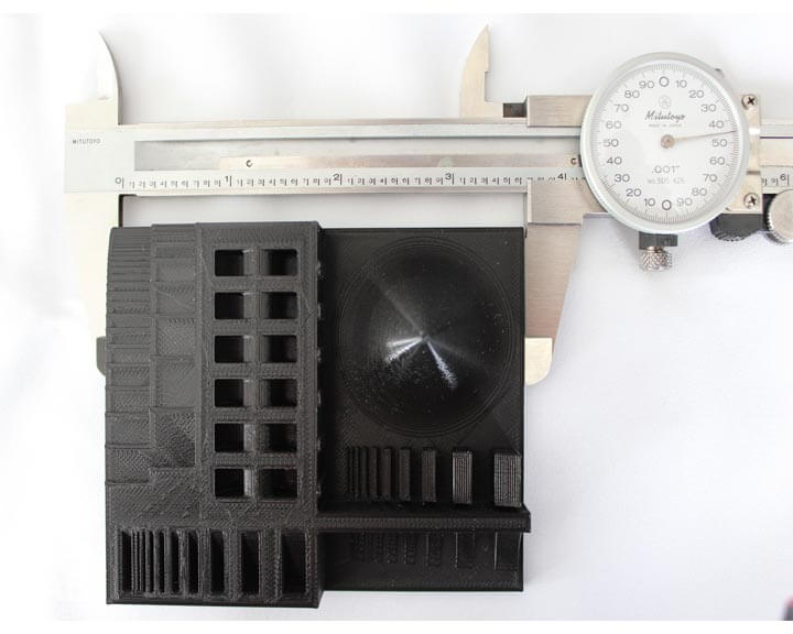
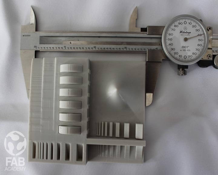
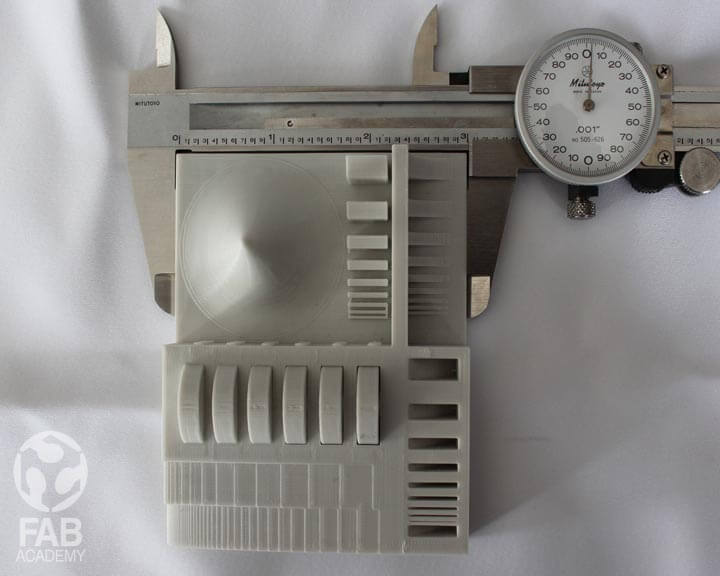
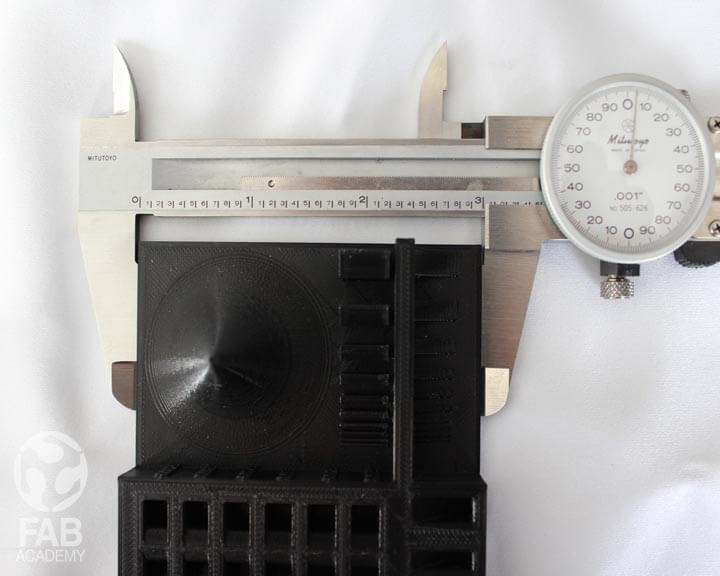
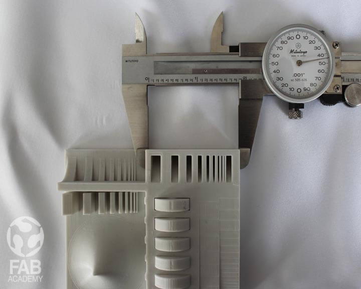
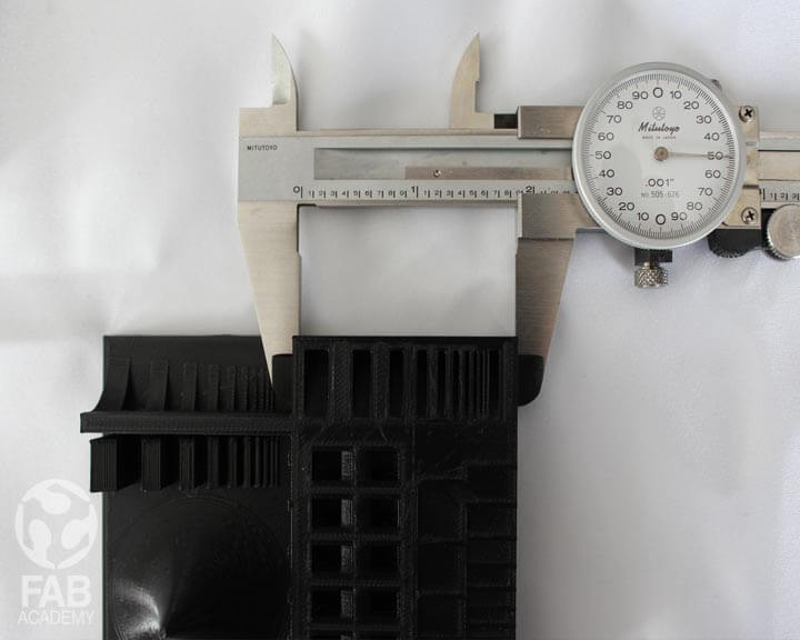
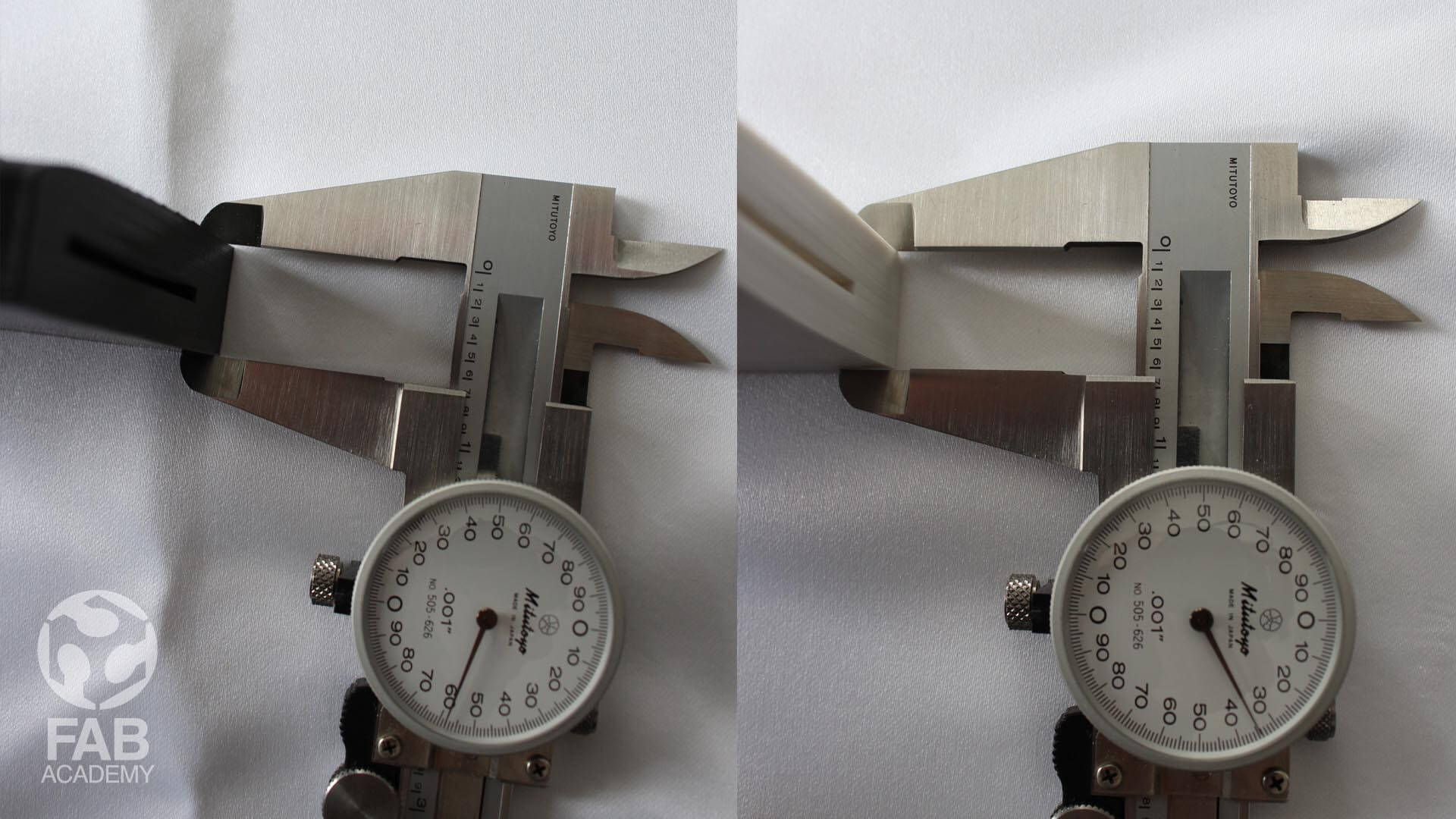
Then after the printing was done we started to compare the end result of both printers and compared the printed items with the original stl file in order to spot the shrinkage level, the accuracy and
precision, all the measurements were taken using a calliper.
However, Doing this group assignment where we print the same model using 2 different 3D printers was really
helpful because of many reasons like it allows me to spot the difference between heated bed and none-heated bed 3D printers,
and it also allow me to better understand the design process for
3D printing in addition to that this helped me in knowing the approximate shrinkage level of the printed parts and how I can adjust the scaling
factor percentage in my CAD apps to match the size of the 3D printed model with the CAD model.
Below are my technical notes on the printing process :
3D PRINTER USED : Ultimaker 3 & Ditto-Pro
FILAMENT USED : PLA Black & White
SOFTWARE USED : CURA & Ditto-Pro
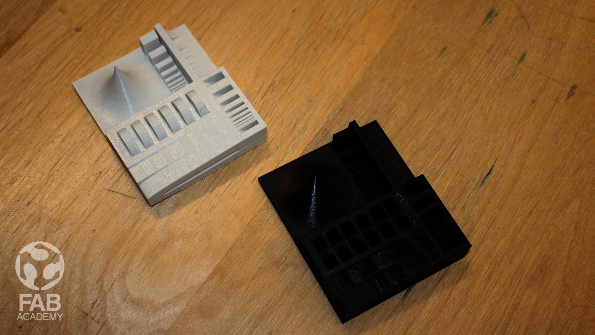
+ The same printing settings were applied to both parts but we had some differences among them like the dimensions and the finishing quality .
Ultimaker gave us a better overall quality than Ditto-Pro.
+ The base was different with a cold print bed we got a mate finish looking texture for the model that was printed with Ditto-Pro please check image # 22 wile with a heated bed the quality was much more better check please image # 22.
+ The dimensions in both prints were different for instance when we measured the length of printed model it was 3.003" for that model that was printed with Ditto-Proand and 3.004" for the model that was printed
with Ultimaker and the same thing applied to the width in both printed items the dimensions were different as well .
My overall conclusion is that 3d printing technology ( additive manufacturing ) is great for rapid prototyping and testing our ideas quickly in addition to that it is very useful for low volume production but it has some limitations when it comes to printing objects
in large format and it lack some precision for example what you see on the computer screen is not what you get in terms of dimensions
and comparing to other traditional production technique for mass production like plastic injections moulding 3D printing is super expensive and slow.
3D SCANNING
SCENE SET-UP AND 3D SCANNING
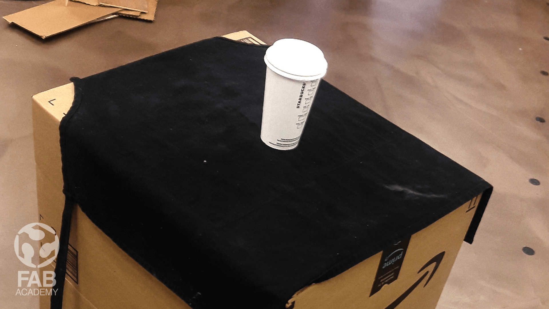
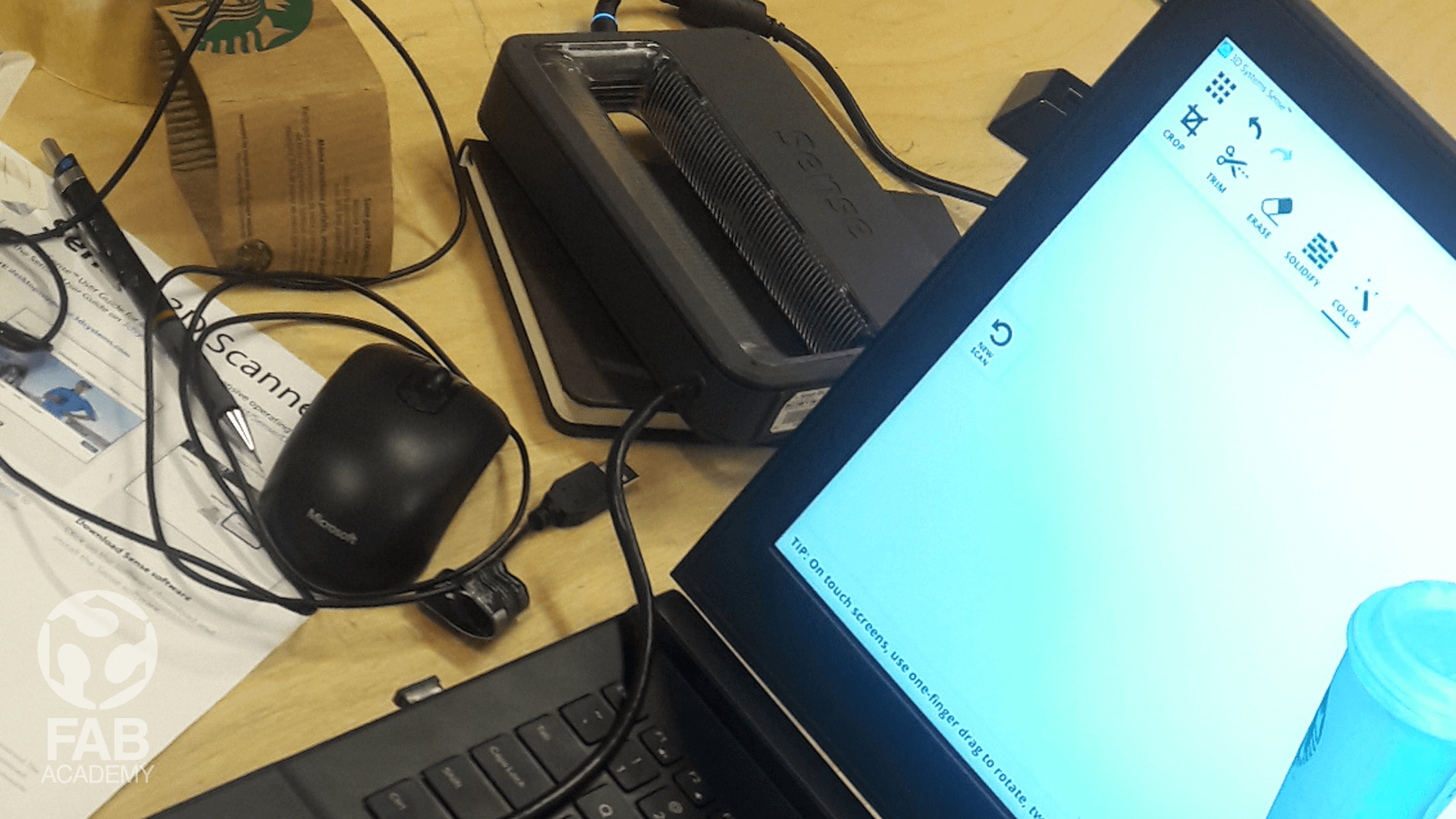
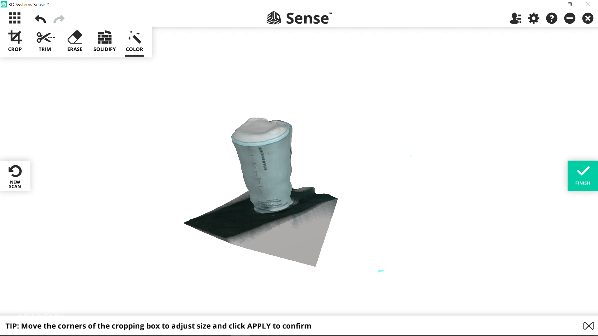
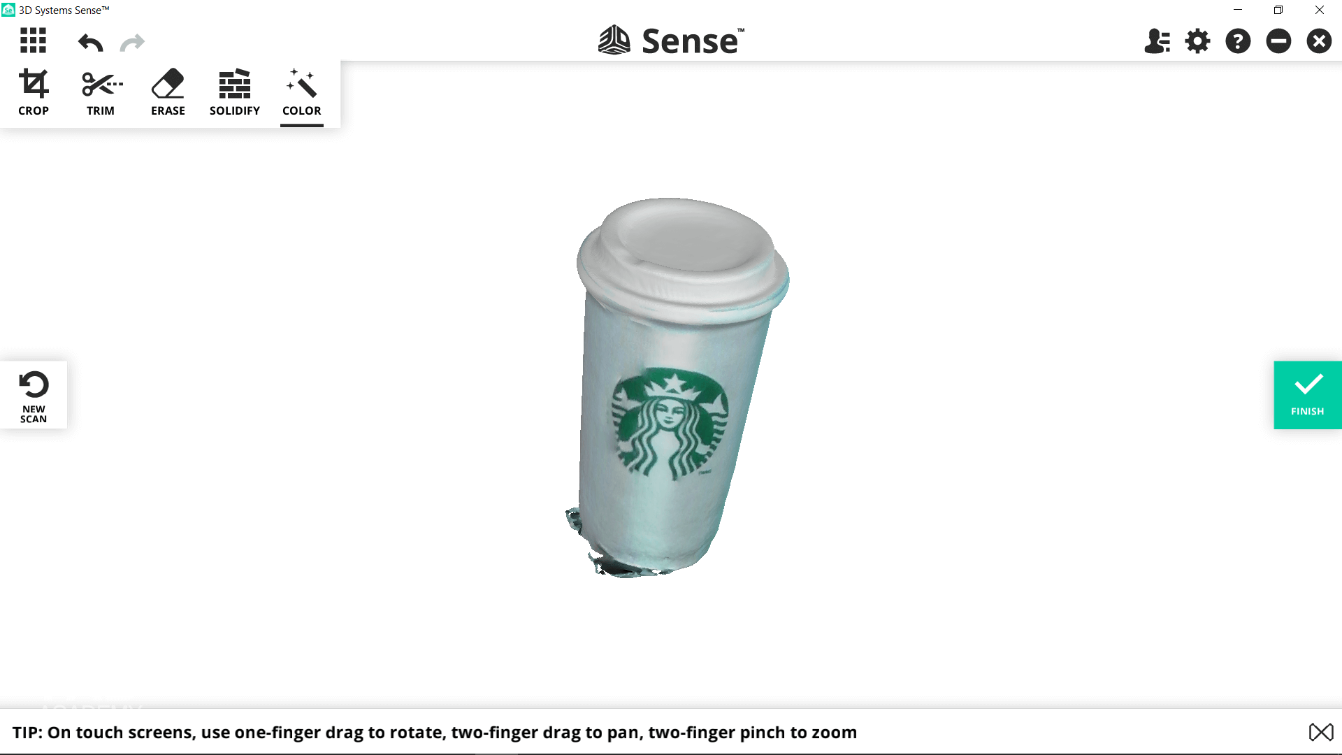
For this assignment I decided to scan a simple object since it was my first time to try 3D scanning so to start with I chose a medium size paper cup. First, I started with downloading Sense software and the necessary drivers for running the scanner. Then I started the process by setting-up the scene so I placed the paper cup on a packaging box that was around 70 cm high in order to rise the object up from the ground level for better scanning and maneuverability while holding the scanner up and moving around the object. However, The first initial attempts went wrong they were choppy or incomplete because I was not feeling very comfortable holing both the laptop and scanner while moving around the model in addition to that I was moving a bit quickly with shaking hands as a result I started getting "Lost Tracking" massages many times so I had to move back and re-capture the previous frames again and again and then when I was done with the scanning process and I started generating the meshes out of the captured data the end result was really bad, the cup was distorted and the surface was bumpy as you see in image #25 the scanner had trouble recognizing what I was trying to scan. So in order to solve this problem I had to repeat the process again, However this time I re-positioned the object and place it directly under the ceiling light source so the object was well-lighted in addition to that, I placed a black fabric under the cup in order to increase the contrast level and isolate the object visually from the surrounding background. And then I started scanning the object again by holding up the scanner and I was pointing it down towards the model in 45º angle as it was recommended by user manual. So while I was doing that the software was building the 3D model simultaneously in real time and the overall look was much more better than the previous tries and it did not take too much time to complete the whole model since he amount of time you'll spend scanning something varies depending on the size and detail of the object itself. My overall experience using the 3D scanner was good I really like this technology and how it opens doors for non 3D artist to generate high end 3D models and 3D assets based on a real world physical model also the software was super user-friendly straight forward and very easy to use all you have to do is to tap "Start to Scan" and the software starts counting down from three before it start capturing the data. I believe I could achieve better results if the scanner was cordless and I noticed that the scanner work best with medium and large size model.
USEFUL TIPS & LINKS
+ HOW TO: USE THE SENSE 3D SCANNER HERE.
DOWNLOAD SECTION
+ 3D MODEL.max DOWNLOAD .
+ CUP.stl DOWNLOAD .
+ 3D_Printer_Tolerance_Test.zip (By www.thingiverse.com ) DOWNLOAD .
+ 3D MODEL.STL DOWNLOAD .